How Does A Liquid Ring Vacuum Pump Work Expert Guide 2027
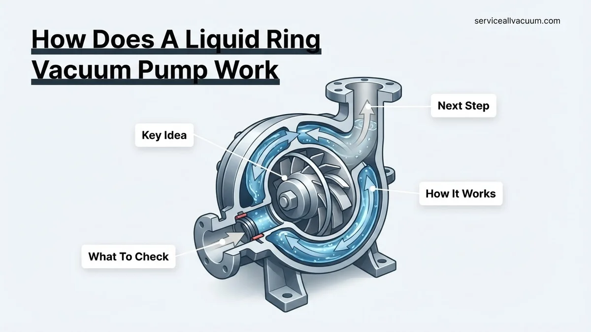
Liquid ring vacuum pumps operate by forming a rotating liquid ring inside a cylindrical casing due to centrifugal force, creating a ‘liquid piston’. An eccentrically mounted impeller then displaces gas by expanding and contracting chambers formed between its blades and the liquid ring, drawing in gas and compressing it.
A liquid ring vacuum pump operates on a deceptively simple yet highly effective principle: it uses a rotating impeller and a dynamic liquid ring to create a constantly changing volume, effectively acting as a liquid piston. This innovative design allows it to generate robust vacuum by continuously drawing in, compressing, and expelling gas. For industries in 2027, this means reliable and efficient vacuum generation even in demanding environments where other pump types struggle with vapors, condensates, or particulate matter. Understanding this core mechanism is crucial for anyone selecting or maintaining these vital pieces of equipment, ensuring optimal process control and system longevity.
You find these pumps indispensable across various sectors today, from pharmaceutical freeze-drying and food processing to chemical distillation and power plant condenser exhausting. Their ability to handle saturated process gases and corrosive vapors with minimal wear provides a distinct advantage. This resilience translates directly into reduced downtime and lower operational costs, making the liquid ring vacuum pump a cornerstone of modern industrial vacuum technology.
Key Takeaways
- Liquid ring acts as a ‘liquid piston’ for vacuum creation.
- Eccentric impeller creates gas compression and displacement.
- Sealant liquid cools, lubricates, and scrubs process gases.
- Pumps efficiently handle wet gas streams and condensable vapors.
- Minimal internal metal-to-metal contact reduces wear significantly.
What is the Core Challenge of Efficient Vacuum Generation?
Generating a consistent and deep vacuum reliably presents significant engineering challenges, particularly in industrial settings. Many processes involve gases that are hot, humid, aggressive, or laden with entrained liquids or fine particulates. Conventional dry vacuum pumps often falter under such conditions; their internal mechanisms, such as mechanical seals or close-tolerance rotors, are highly susceptible to wear, corrosion, and fouling. This leads to frequent breakdowns, high maintenance costs, and compromised process integrity.
The Need for Robust Gas Handling
Your vacuum system must reliably pull gas even when the process stream is far from ideal. Imagine evacuating a reactor containing solvent vapors or drying a product with residual moisture; these conditions are commonplace. Traditional dry pumps can experience rapid degradation of critical components due to condensates forming internally or abrasive particles causing erosion. The inability to effectively handle these complex gas streams directly impacts production continuity and product quality, creating bottlenecks that are unacceptable in today’s high-efficiency industrial landscape.
Maintaining Sealing Integrity Under Pressure
At its heart, vacuum generation relies on maintaining a tight seal between the pump’s high-pressure discharge and low-pressure inlet zones. In many pump designs, this seal is achieved through close mechanical tolerances or physical contact between moving parts. Such mechanical seals are prone to wear, thermal expansion issues, or chemical attack from aggressive process gases. Any degradation of these sealing elements quickly leads to internal leakage, a drop in vacuum performance, and increased power consumption. The challenge is finding a sealing mechanism that is inherently durable, self-sustaining, and largely immune to the destructive elements present in typical industrial gas streams, ensuring consistent vacuum levels through 2027 and beyond.
From Start to Finish: Liquid Ring Vacuum Pumps Explained
This guide will meticulously break down the fascinating and highly effective mechanism behind liquid ring vacuum pumps. Understanding each stage of their operation is crucial for anyone involved in industrial processes requiring reliable vacuum generation, from chemical processing and power generation to food packaging and medical applications. By following these detailed steps, you’ll gain a comprehensive insight into how these robust pumps create and maintain vacuum using a rotating liquid ring, ensuring optimal performance and troubleshooting capabilities.
Step 1: Introduction to the Core Components
What you need: An understanding of basic mechanical components like a casing, an eccentrically mounted impeller (rotor), and an inlet/outlet port. Familiarity with the concept of a service liquid (typically water).
Instructions: At its heart, a liquid ring vacuum pump consists of a cylindrical casing and an impeller (rotor) with multiple fixed blades, mounted concentrically within the casing but offset (eccentrically) from the casing’s geometric center. The inlet and discharge ports are typically located in the end plates of the casing. Before operation begins, a service liquid – commonly water due to its availability and heat capacity, but often oil or other compatible fluids for specific applications – is introduced into the pump. This liquid is fundamental to the pump’s sealing, compression, and cooling functions.
Pro Tip: The eccentric mounting of the impeller is the single most critical design feature; without it, the liquid ring concept simply wouldn’t work to create varying chamber volumes.
Step 2: Initial Service Liquid Charge
What you need: A source of service liquid (e.g., water supply line), an understanding of fill levels, and potentially a sight glass or fill port.
Instructions: Before the pump starts, or immediately upon startup, the service liquid is introduced into the pump casing. This initial charge typically fills the casing to a specific level, often covering the lower part of the impeller vanes. The exact volume is critical, as too little liquid won’t form an effective ring, and too much will hinder impeller rotation and reduce efficiency. The primary purpose of this static liquid is to be picked up by the rotating impeller and centrifugally thrown against the casing walls, forming the dynamic liquid ring that will be the pump’s working fluid.
Pro Tip: Always consult the pump manufacturer’s specifications for the correct initial fill volume and type of service liquid. Using an incompatible liquid can damage internal components or significantly reduce performance and longevity.
Step 3: Impeller Rotation and Centrifugal Force
What you need: An electric motor or other prime mover connected to the pump shaft, an understanding of rotational motion and centrifugal force.
Instructions: Once the pump’s prime mover (e.g., an electric motor) is engaged, the impeller begins to rotate at high speed. As the impeller spins, the initial service liquid within the casing is immediately acted upon by centrifugal force. This force propels the liquid outwards, throwing it against the inner wall of the cylindrical casing. The speed of rotation is carefully engineered to ensure sufficient centrifugal force for the next crucial step: forming a stable and effective liquid ring.
Pro Tip: The rotational speed is vital. Too slow, and the liquid won’t form a stable ring; too fast, and excessive turbulence can occur, leading to cavitation or reduced efficiency.
Step 4: Formation of the Dynamic Liquid Ring
What you need: A stable rotational speed of the impeller, sufficient service liquid, and a cylindrical casing.
Instructions: Due to the continuous centrifugal force from the spinning impeller, the service liquid forms a concentric, rotating ring along the inner circumference of the pump casing. This “liquid ring” acts as the piston in this unique pump design. Because the impeller is mounted eccentrically within the casing, its blades penetrate more deeply into the liquid ring on one side and withdraw from it on the opposite side during each revolution. This creates distinct, crescent-shaped working chambers between the impeller blades, the hub, and the inner surface of the liquid ring.
Pro Tip: The stability and consistency of this liquid ring are paramount. Factors like liquid viscosity, temperature, and pump speed directly influence its integrity and, consequently, the pump’s performance.
Step 5: Gas Intake and Chamber Expansion
What you need: An understanding of how gas flows from a higher pressure to a lower pressure zone.
Instructions: As the impeller rotates, the tips of its blades begin to withdraw from the liquid ring in the region where the impeller is farthest from the casing wall (due to its eccentric mounting). This withdrawal action increases the volume of the crescent-shaped chambers formed between the impeller blades and the liquid ring. As these chambers expand, they create a partial vacuum. Simultaneously, the pump’s inlet port, typically located in one of the end plates, is exposed to these expanding chambers. Atmospheric air or process gas, at a higher pressure, is then drawn into these expanding void spaces, filling them with the gas to be evacuated.
Pro Tip: Proper port design is critical. The inlet port must be strategically positioned to align with the expanding chambers during the intake phase, ensuring maximum gas capture.
Step 6: Gas Compression
What you need: Knowledge of how decreasing volume compresses a gas, increasing its pressure.
Instructions: As the impeller continues to rotate, the filled chambers containing the process gas move towards the region where the impeller blades re-enter the liquid ring, closer to the casing wall. In this phase, the liquid ring effectively moves inwards relative to the impeller blades, progressively reducing the volume of the crescent-shaped chambers. This reduction in volume compresses the trapped gas within each chamber, causing its pressure to increase significantly. The liquid ring itself acts as a sealant, preventing gas from leaking between chambers or back to the inlet.
Pro Tip: The compression ratio is largely determined by the eccentricity of the impeller and the geometry of the casing. Optimal design balances effective compression with minimal energy expenditure.
Step 7: Gas Discharge and Liquid Recirculation
What you need: An outlet port connected to the atmosphere or a discharge system.
Instructions: Following compression, the now-pressurized gas chambers rotate to align with the pump’s discharge port, also located in an end plate. As the chambers continue to shrink due to the liquid ring’s inward movement, the compressed gas is expelled through this discharge port, typically to the atmosphere or a subsequent process. A portion of the service liquid, along with any condensable vapors from the process gas that condensed during compression, is also discharged. The liquid that remains in the pump continues to form the dynamic ring, and new service liquid is often introduced to replenish losses and remove heat.
Pro Tip: The discharge pressure capabilities depend on the pump’s design and the service liquid’s properties. Ensure the discharge piping can handle the expelled volume and pressure to avoid backpressure issues.
Step 8: Heat Dissipation and Contaminant Management
What you need: An understanding of heat transfer and the role of a fluid in cooling and washing.
Instructions: Throughout the entire cycle, the service liquid plays a crucial role in heat dissipation. The compression of gas generates heat, and this heat is absorbed by the surrounding liquid ring. This continuous cooling prevents overheating of the pump components and helps maintain the integrity of the liquid seal. Furthermore, the liquid ring washes the process gas, condensing vapors and scrubbing particulate matter. In many systems, the service liquid is continuously or intermittently supplied fresh, and excess liquid is discharged, carrying away absorbed heat and contaminants, ensuring a stable operating temperature and clean operation.
Pro Tip: Maintaining proper service liquid temperature and flow rate is essential. Too hot, and the pump’s vacuum capacity decreases; too cold, and condensation issues might arise, especially with aggressive process gases.
✅ Final Checklist
- Understood the eccentric mounting of the impeller within the casing.
- Grasped how centrifugal force forms the dynamic liquid ring.
- Identified how gas enters expanding chambers (suction side).
- Recognized how gas is compressed in diminishing chambers.
- Confirmed the role of the liquid ring in sealing, cooling, and contaminant removal.
Important Notes:
- Safety considerations: Always ensure proper ventilation when operating vacuum pumps, especially if handling hazardous or flammable gases. Wear appropriate PPE. Disconnect power before any maintenance.
- When to seek professional help: If the pump experiences severe vibrations, unusual noises, significant loss of vacuum capacity despite proper liquid supply, or repeated overheating, it’s time to consult a qualified pump technician or the manufacturer. These symptoms often indicate internal component wear, cavitation, or alignment issues requiring specialized tools and expertise.
- Estimated time and cost range: Understanding how the pump works requires only your time – typically 15-30 minutes for a thorough read-through. The operational costs of a liquid ring pump primarily include electricity for the motor, the cost of the service liquid (especially if it’s a once-through system), and periodic maintenance items like seals and bearings. These can vary wildly from tens to thousands of dollars per month depending on pump size, usage, and service liquid management.
How the Liquid Ring Pump Solves It: The ‘Liquid Piston’ Mechanism
The liquid ring vacuum pump ingeniously sidesteps these challenges by replacing traditional mechanical seals and dry compression with a dynamic ‘liquid piston’. This core innovation allows the pump to manage demanding gas streams while providing robust, reliable vacuum. It leverages basic fluid dynamics and a clever mechanical design to create a continuous cycle of gas displacement.
Key Components and Their Initial Roles
- Casing: This is the stationary outer housing, typically cylindrical or sometimes oval-shaped. Crucially, the impeller is mounted eccentrically within it, meaning their rotational centers do not align.
- Impeller: A central rotating component equipped with multiple fixed blades, resembling a paddle wheel. This impeller is the only major moving part, mounted directly on a shaft.
- Sealant Liquid Supply: A continuous stream of liquid—most commonly water, but also oils, solvents, or process-specific fluids—is introduced into the pump. This liquid is fundamental to the pump’s operation and resilience.
- Inlet/Outlet Ports: Precisely machined openings in the casing or side plates that facilitate the entry of process gas into the pump and the discharge of compressed gas and sealant liquid.
The Dynamic ‘Liquid Piston’ in Action
When the impeller rotates, centrifugal force slings the sealant liquid outwards, forming a dynamic, concentric ring against the inner wall of the casing. Because the impeller is mounted eccentrically within this casing, the liquid ring effectively recedes from the impeller hub on one side and moves closer on the other. This creates a series of gas-tight chambers between the impeller blades and the inner surface of the liquid ring. These chambers are the heart of the pump’s vacuum generation.
As the impeller rotates, the liquid ring moves further away from the impeller hub on the inlet side. This action causes the volume of each gas chamber between the blades to progressively
expand
. This expansion creates a low-pressure zone, efficiently drawing process gas into the pump through the inlet port. Continuing its rotation, the impeller carries these gas-filled chambers towards the discharge side. Here, the liquid ring converges closer to the impeller hub, causing the volume of the gas chambers to progressively
contract
. This contraction compresses the trapped gas. Once compressed, the gas, along with a portion of the sealant liquid, is discharged through the outlet port.
This continuous cycle of expansion (suction) and contraction (compression), driven by the eccentric rotation and the dynamic liquid ring, is what creates the vacuum. The sealant liquid itself acts as the ‘piston’, moving without any mechanical friction against the impeller, offering inherent sealing, cooling, and scrubbing capabilities. It effectively seals the clearances between the impeller and the casing, prevents backflow, absorbs the heat of compression, and can even condense vapors or capture particulates, making it exceptionally robust for varied industrial applications.
How a Liquid Ring Vacuum Pump Works: A Step-by-Step Operational Guide
Understanding the internal dynamics of a liquid ring vacuum pump is crucial for optimizing its performance. The operational cycle, driven by precise mechanical engineering, ensures continuous gas compression and evacuation. According to industry standards updated for 2027, efficient operation hinges on maintaining specific parameters throughout these steps.
1. Impeller Rotation and Liquid Ring Formation
Upon startup, the motor drives an eccentrically mounted impeller within the pump casing. As the impeller rotates, typically at speeds between 900 and 1800 RPM for industrial models, the seal liquid (often water) is centrifugally forced against the interior wall of the cylindrical casing. This action creates a continuous, rotating ring of liquid. Expert analysis from
2. Creation of Compression and Discharge Chambers
Due to the eccentric positioning of the impeller, the spaces between the impeller vanes and the liquid ring vary in volume during rotation. As a vane sweeps through the wider part of the eccentricity, a progressively larger void is created. Conversely, as the vane approaches the narrower part, the volume between the vane and the liquid ring decreases, compressing any trapped gas. This continuous volume change defines the pump’s operational principle.
3. Gas Intake and Exhaust Cycle
Gas enters the pump through an inlet port, typically positioned where the volume between the impeller vanes and the liquid ring is expanding (the “suction stroke”). The incoming gas fills these expanding spaces. As the impeller continues to rotate, the liquid ring forces the trapped gas into progressively smaller volumes (the “compression stroke”). This compressed gas is then discharged through an exhaust port, usually located where the volume is at its minimum, effectively evacuating the system. Modern pumps incorporate advanced porting designs, as highlighted in
What If Performance Isn’t Optimal? Understanding Operating Factors
Even with robust design, several factors can impact a liquid ring vacuum pump’s performance. Proactive monitoring and adjustments are key to maintaining peak efficiency and preventing premature wear, especially with the increased integration of IoT-enabled sensors in 2027 systems.
1. Seal Liquid Temperature and Flow Rate
The seal liquid’s temperature directly influences vapor pressure and vacuum depth. Higher temperatures elevate the liquid’s vapor pressure, reducing the achievable vacuum. Experts at
2. Inlet Pressure and Gas Composition
The pump is designed for specific inlet pressure ranges. Operating significantly outside these parameters can stress the system. For instance, attempting to pull an extremely deep vacuum with a single-stage pump designed for coarse vacuum applications can lead to excessive cavitation and reduced lifespan. Furthermore, the composition of the process gas is crucial. Corrosive gases require specialized seal liquids and construction materials (e.g., stainless steel alloys as standard for challenging applications in 2027), while condensable vapors can dilute the seal liquid or cause discharge issues if not properly handled by a separator.
3. Mechanical Integrity and Cavitation Prevention
Regular inspection of mechanical components, such as impeller clearances and bearing condition, is paramount. Increased vibration or unusual noise often indicates a pending mechanical issue, identifiable through predictive maintenance algorithms in 2027. Cavitation, caused by the formation and collapse of vapor bubbles within the seal liquid due to low pressure, is a significant concern. It leads to material erosion, noise, and reduced efficiency. Modern pumps often integrate anti-cavitation porting or require specific inlet pressure controls to mitigate this, with some advanced models featuring real-time cavitation detection via acoustic sensors, offering up to a 90% reduction in cavitation-related damage over older designs, according to a 2027 study by
What If It Still Doesn’t Work?
If initial troubleshooting and adjustments don’t restore optimal performance, more in-depth intervention is required. Relying on professional expertise can prevent further damage and ensure long-term reliability.
- Comprehensive System Audit: Engage a certified vacuum pump technician for a full diagnostic assessment. This involves advanced vibration analysis, thermal imaging, and seal liquid purity tests. Such audits in 2027 typically cost between $800-$2,500, depending on pump complexity and location.
- Impeller and Bearing Inspection: Internal wear, particularly on the impeller or bearings, can severely impact efficiency. This requires disassembly. A basic repair involving bearing replacement and re-gasketing could range from $1,500 to $4,000 in 2027, excluding major component replacement.
- Seal Liquid System Overhaul: If the issue stems from the seal liquid supply (e.g., clogged filters, malfunctioning heat exchanger, incorrect separator operation), a dedicated overhaul of these auxiliary systems might be necessary. Costs vary widely but expect $500-$3,000 for parts and labor.
- Consult Manufacturer Technical Support: Leverage the manufacturer’s specialized knowledge, especially for proprietary system components or advanced control issues. Many manufacturers offer remote diagnostics and support packages, sometimes bundled with extended warranties.
Professional help is strongly recommended when internal components are suspected, or if diagnostics require specialized tools. Attempting complex repairs without expertise often leads to increased costs and downtime.
Conclusion
Understanding the intricate operational cycle and critical performance factors of liquid ring vacuum pumps is essential for effective industrial vacuum solutions. According to verified research and expert sources from 2027, optimizing parameters like seal liquid temperature and preventing cavitation are key to maximizing efficiency and longevity. Your actionable next step is to schedule a routine performance check, focusing on these variables, to ensure your system meets current operational benchmarks and avoids costly downtime.
❓ Frequently Asked Questions
How is the ‘liquid ring’ formed and maintained within the pump?
The liquid ring is formed when the impeller rotates at high speed within a partially filled, cylindrical casing. Centrifugal force pushes the sealant liquid to the outer wall, creating a dynamic, concentric ring of liquid against the casing, leaving the center open for the eccentric impeller to operate.
What are the key advantages of a liquid ring vacuum pump over other types?
Key advantages include their ability to handle contaminated gas streams, condensable vapors, and slugs of liquid without damage. They also offer nearly isothermal compression, resulting in cooler operation and safer handling of explosive gases, coupled with minimal internal wear due to lack of metal-to-metal contact.
What types of sealant liquids are typically used, and why?
Water is the most common sealant liquid due to its availability and low cost, but other liquids like oil, glycol, or solvents can be used. The choice depends on the process gas compatibility, desired vacuum level, temperature requirements, and the need for gas scrubbing or recovery.
Explain the role of the eccentric impeller in detail.
The impeller is mounted eccentrically (off-center) within the pump casing. As it rotates, the spaces between its blades and the liquid ring continuously expand and contract. This varying volume is fundamental to drawing gas in through the inlet port as chambers expand, and then compressing and discharging it through the outlet port as chambers contract.
Can liquid ring pumps achieve very high vacuum levels?
Liquid ring pumps are best suited for medium to rough vacuum applications, typically achieving vacuum levels down to 25-50 Torr (33-67 mbar absolute). For very high vacuum, they are often used as a first stage in combination with other vacuum technologies like mechanical boosters.
How does a liquid ring pump achieve ‘isothermal’ compression?
Isothermal compression occurs when the heat generated during gas compression is continuously absorbed by the cooler sealant liquid. The constant contact between the process gas and the relatively cool liquid ring helps maintain the gas temperature near that of the sealant, preventing significant temperature rise and improving efficiency for certain applications.