How to Test Vacuum Tubes Expert Step-by-Step Guide 2027
Testing vacuum tubes is crucial for maintaining vintage audio gear and electronics. This guide provides step-by-step instructions for diagnosing tube health, covering essential safety precautions and equipment like multimeters and tube testers, enabling you to accurately assess functionality.
Testing vacuum tubes yourself is a critical skill for any enthusiast or professional maintaining tube-based equipment in 2027. It allows you to quickly determine a tube’s health, identify common failures like shorts or weak emission, and prevent potential damage to your valuable amplifiers or gear. Knowing how to perform these physical tests, what equipment you need, and how to interpret the results will save you time, money, and frustration. This guide cuts directly to the practical steps, ensuring you can confidently assess your tube collection.
Understanding the condition of your tubes isn’t just about troubleshooting; it’s about proactive maintenance. A dying tube can often degrade performance long before it completely fails, and identifying these issues early can keep your audio pristine or your industrial equipment running smoothly. Let’s get started on bringing clarity to your tube testing routine.
Key Takeaways
- Prioritize safety; tubes operate with dangerous high voltages.
- Use a multimeter for basic filament continuity checks first.
- Visual inspection often reveals physical damage or shorts.
- Emission testers provide basic health but not full performance.
- Transconductance testers offer detailed performance metrics.
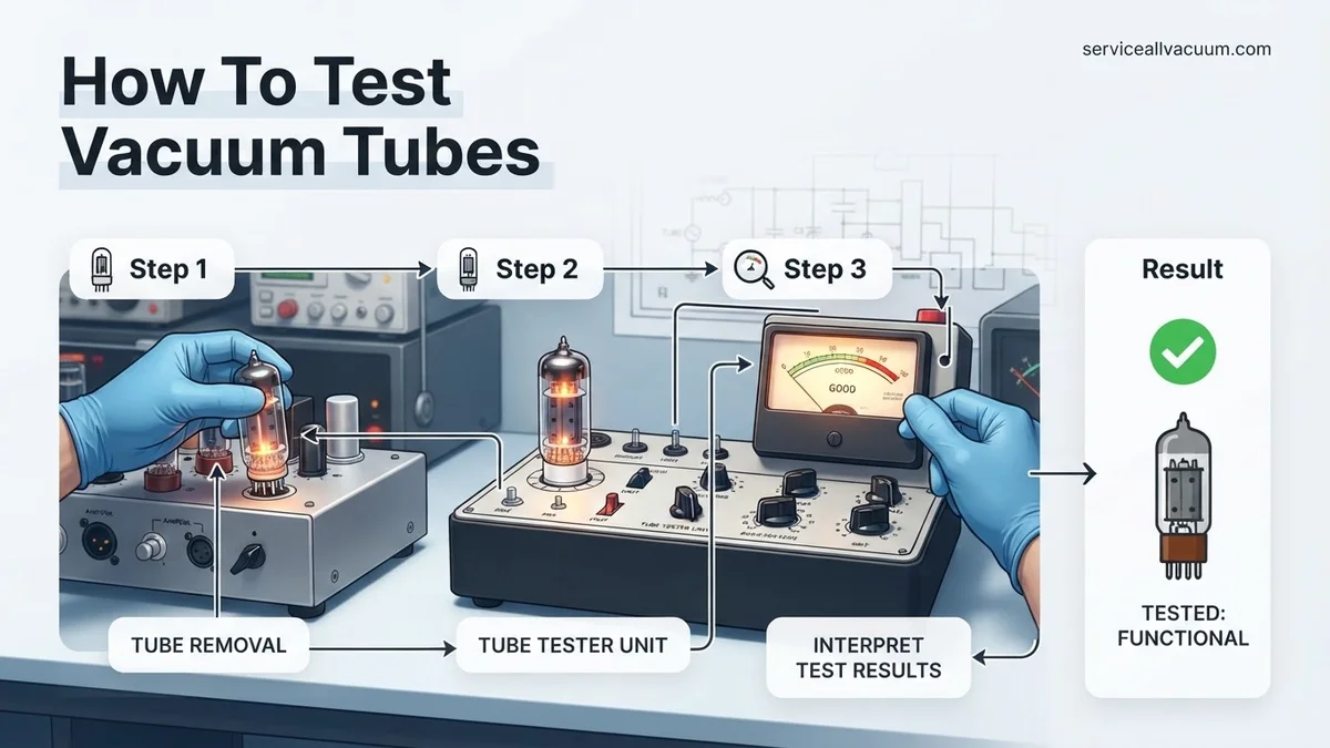
What Causes Vacuum Tube Failure (and Why Testing Helps)
Vacuum tubes, despite their robust appearance, are complex devices susceptible to several common failure modes that impact performance. By 2027, while manufacturing techniques have improved, tubes still wear out. The primary reasons for failure include filament breaks, internal shorts, and weakened cathode emission. Each of these can lead to anything from subtle performance degradation to catastrophic equipment failure if not detected.
Common Tube Failure Modes
- Open Filaments: The filament is the heater element that glows, enabling electron emission. If it breaks, the tube simply won’t heat up, and thus, won’t operate at all. This is often an obvious failure.
- Internal Shorts: This occurs when internal elements (like the plate, grid, or cathode) touch each other, usually due to physical shock or manufacturing defects. Shorts can cause immediate damage to your equipment’s power supply or transformers.
- Weak Emission: Over time, the cathode coating degrades, reducing its ability to emit electrons. This results in decreased amplification, distortion, and a general lack of power from the tube. It’s a common cause of “tired” sounding equipment.
- Gas Leaks (Gassy Tubes): A compromise in the vacuum integrity allows residual gas inside the tube, leading to erratic operation, arcing, and premature failure. You might notice a blue glow that isn’t supposed to be there.
The Proactive Power of Testing
Testing acts as a crucial diagnostic tool. Identifying an open filament with a simple multimeter prevents you from installing a dead tube. A shorts test on a tube tester can pinpoint internal element contact before it damages your amplifier’s costly components. Furthermore, emission tests reveal weakening tubes long before they completely fail, allowing for timely replacement and consistent performance. This proactive approach ensures your tube gear always performs at its best and avoids costly repairs associated with sudden tube failures.
How to Test Vacuum Tubes Like a Pro: A Practical Walkthrough
Welcome to this comprehensive guide on how to test vacuum tubes! Understanding the condition of your tubes is crucial for maintaining the performance and longevity of vintage audio equipment, guitar amplifiers, and other tube-powered devices. This guide will walk you through essential techniques, from simple visual checks to using specialized tube testers, ensuring you can accurately diagnose potential issues and make informed decisions about your cherished vacuum tubes.
Step 1: Prioritize Safety & Prepare Your Workspace
What you need: Safety goggles, insulated gloves, a clean and well-lit workspace, tube puller (optional), schematic/tube data sheet (optional but recommended). Ensure the equipment housing the tubes is completely unplugged and has been off for at least an hour to allow capacitors to discharge and tubes to cool down. High voltages can be present even after power-off.
Instructions: Before touching any tubes or opening any equipment, always confirm that the power cord is disconnected from the wall outlet. Use a tube puller for difficult-to-remove tubes to prevent bending pins or cracking the glass. Place tubes carefully on a soft, non-conductive surface to prevent damage. Having the tube’s datasheet can help identify its specific pinout, heater voltage, and typical operating parameters, which will be useful for more advanced testing.
Pro Tip: Never work on live tube equipment unless you are a trained professional with appropriate safety gear. Always assume high voltage is present until you have confirmed otherwise with a high-voltage probe.
Step 2: Perform a Thorough Visual Inspection
What you need: Good lighting (e.g., a desk lamp or flashlight), magnifying glass (optional), soft cloth.
Instructions: Carefully examine the glass envelope of the tube for any cracks, chips, or milky-white spots. A milky-white or purple/brown discoloration inside the tube indicates that the vacuum has been lost, rendering the tube useless. This is often seen on the getter flash – the shiny silver, mirror-like coating inside the top or side of the tube. A good getter should be largely opaque and silver. Check for any loose internal components, rattling sounds when gently shaken (not recommended for all tubes), or bent/corroded pins. Also, inspect the filament; sometimes, a broken filament wire is visible as a tiny, disconnected strand within the tube structure.
Pro Tip: A perfectly clear getter flash with no silvering might indicate a ‘new’ tube that hasn’t been fired, or one with manufacturing defects. A faint purple glow during operation (not testing) can sometimes indicate gas inside the tube, which is generally undesirable.
Step 3: Clean Tube Pins and Socket Connections
What you need: DeoxIT D5 or similar contact cleaner, small brass brush (e.g., dental brush or fine wire brush), cotton swabs, lint-free cloth.
Instructions: Corrosion and oxidation on tube pins and their corresponding socket contacts can lead to poor electrical connections, erratic performance, and even intermittent tube failures. Spray a small amount of DeoxIT D5 directly onto the tube pins. Use the brass brush to gently scrub each pin, ensuring you remove any visible grime or oxidation. For the tube sockets, spray cleaner onto a cotton swab and carefully insert it into each pin receptacle, twisting to clean the internal contacts. Allow the cleaner to evaporate completely before reinserting the tube or applying power. This step ensures reliable contact during testing and operation.
Pro Tip: Avoid over-saturating pins or sockets with cleaner, as excess liquid can spread to other components. For very stubborn corrosion, fine-grit sandpaper (600+ grit) can be used very gently on pins, but only as a last resort and with extreme care not to remove too much material.
Step 4: Conduct Filament Continuity and Short Tests with a Multimeter
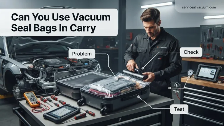
What you need: Digital Multimeter (DMM) with continuity and resistance (Ohms) settings, tube datasheet/pinout diagram.
Instructions: Refer to the tube’s datasheet to identify the filament pins (usually indicated as ‘heater’ or ‘filament’). Set your DMM to the lowest resistance (Ohms) range or to the continuity setting (which often beeps for continuity). Place one probe on one filament pin and the other probe on the corresponding filament pin. For a healthy tube, you should get a low resistance reading (typically 2-100 Ohms, depending on the tube type) or a continuity beep. An open circuit (OL or no reading) indicates a broken filament. Next, test for shorts: keep one probe on a filament pin and touch the other probe to all other pins one by one, and then to the tube’s plate, grid, and cathode pins (if accessible or if an external conductive coating is present). Any reading other than open circuit (OL) indicates a short, which is a critical failure.
Pro Tip: Ensure your multimeter’s batteries are fresh for accurate resistance readings. Always perform these tests with the tube cold and completely out of circuit, as residual voltage or other components can skew readings.
Step 5: Utilize a Dedicated Vacuum Tube Tester (Part 1: Setup & Initial Checks)
What you need: A dedicated vacuum tube tester (e.g., Hickok, Sencore, Maxi-Matcher, or modern digital tester), tube data roll chart for vintage testers, tube being tested, tube puller.
Instructions: A dedicated tube tester provides much deeper diagnostics than a multimeter. First, select the correct socket on your tester for the tube type (e.g., 9-pin miniature, octal). If using a vintage tester with a roll chart, locate your specific tube type and carefully dial in all the required settings: filament voltage (e.g., 6.3V, 12.6V), plate voltage, grid voltage, screen voltage, and any bias settings. Confirm the tester’s internal switches are set according to the chart for shorts, grid leakage, and emission/transconductance tests. Ensure the tube is inserted firmly but gently into the correct socket, aligning the keyway or pin gap. Allow the tube to warm up for at least 30-60 seconds after inserting, before proceeding with tests.
Pro Tip: Always double-check your tester settings against the roll chart or manual before inserting the tube and powering on the tester. Incorrect settings, especially filament voltage, can damage tubes or the tester itself. For new tubes, test them to establish a baseline for future reference.
Step 6: Utilize a Dedicated Vacuum Tube Tester (Part 2: Execution & Interpretation)
What you need: The tube tester, the warmed-up tube.
Instructions: With the tube warmed and settings configured, begin with the shorts test. Most testers have a momentary button or switch for this; any flicker or movement on the meter indicates an internal short, meaning a bad tube. Next, perform the grid leakage (sometimes called ‘gas’) test. Excessive current on this test indicates internal gas, which can cause noise and instability. Finally, conduct the main emission or transconductance (mutual conductance) test. Emission testers measure the cathode’s ability to emit electrons, while transconductance testers measure the tube’s amplification factor. Compare the reading to the ‘minimum good’ or ‘new’ values provided on the roll chart. A reading significantly below the minimum indicates a weak or failing tube; a reading far above ‘new’ might suggest a manufacturing inconsistency or a tube designed for slightly different parameters, but generally, higher is better.
Pro Tip: Tube testers, especially vintage ones, can have variations in readings. Don’t rely solely on one test. A tube that passes the ‘good’ threshold but is at the very bottom might still be functional but nearing the end of its useful life. Consistency across multiple tests (shorts, gas, emission/transconductance) is key.
Step 7: Consider In-Circuit Substitution Testing (If No Tester Available)
What you need: A known good, compatible tube (same type and characteristics), the equipment with the suspected faulty tube, basic tools to access the tubes (e.g., screwdriver).
Instructions: If you don’t have access to a dedicated tube tester, substitution is a practical method. Ensure the equipment is completely unplugged and cooled down (refer to Step 1). Carefully remove the suspected faulty tube using a tube puller if necessary. Insert the known good, compatible tube into the same socket. Re-power the equipment and observe if the issue is resolved. For instance, if an amplifier was producing distorted sound from a specific channel, and swapping the preamp tube in that channel resolves the issue, you’ve likely identified the culprit. This method is effective but requires a working spare tube of the exact same type and is best used after performing visual and multimeter checks.
Pro Tip: Always swap one tube at a time to isolate the problem effectively. Ensure the replacement tube is indeed ‘known good’ – ideally, tested on a reliable tester or confirmed working in another piece of equipment. Never substitute tubes of different types or with different pinouts, as this can cause damage to the equipment.
✅ Final Checklist
- All power is disconnected and capacitors are discharged before handling tubes.
- Visual inspection for physical damage, getter integrity, and internal shorts is complete.
- Tube pins and sockets have been cleaned for optimal contact.
- Filament continuity and inter-element shorts tested with a multimeter (if applicable).
- Tube tester settings correctly applied for the specific tube type (if using a tester).
- Tube tester readings interpreted against ‘good’ parameters for emission/transconductance and gas.
Important Notes:
- Safety considerations: Vacuum tube equipment operates at extremely high voltages (200V-500V or more), which can be lethal. Always unplug equipment and allow ample time for capacitors to discharge before touching internal components or tubes. Use insulated tools and never work alone.
- When to seek professional help: If you encounter complex issues, are unsure about safety procedures, or lack the necessary testing equipment, it is always best to consult a qualified technician. Attempting repairs beyond your skill level can be dangerous and cause further damage.
- Estimated time and cost range: Visual inspection and multimeter tests can take 5-15 minutes per tube and cost as little as $20-$100 for a basic multimeter. Using a dedicated tube tester can take 10-30 minutes per tube, and testers themselves can range from $100 for basic emission testers to $1000+ for professional transconductance models.
How to Test Vacuum Tubes: Step-by-Step Guide 2027
Accurately testing vacuum tubes requires a methodical approach, starting with safety and progressing through various diagnostic checks. By 2027, while advanced digital testers exist, the fundamental principles of testing remain the same. This guide focuses on practical, accessible methods for assessing tube health, primarily using a multimeter and an entry-level tube tester.
1. Prioritize Safety: Your First Step
Before handling any vacuum tubes, especially when working with live equipment or a tube tester, safety is paramount. Tubes can be fragile, and the equipment they power often involves lethal voltages.
- Always Disconnect Power: Ensure your amplifier or tube tester is unplugged from the wall socket before inserting or removing tubes.
- Discharge Capacitors: If working inside an amplifier, high-voltage capacitors can retain a charge even when unplugged. Learn safe discharge procedures or consult a qualified technician.
- Wear Protective Eyewear: In rare cases, a tube can crack or implode. Eye protection is a simple, effective safeguard.
- Handle Tubes Carefully: Tubes can be hot. Use a cloth or gloves if they’ve been recently powered. Avoid touching the glass envelope directly as oils from your skin can create hot spots, reducing tube life.
2. Initial Checks: Visual Inspection & Multimeter
Many common tube issues can be identified without a dedicated tube tester, just by careful observation and a simple multimeter.
- Visual Inspection:
- Glass Envelope: Check for cracks, chips, or milky-white spots (indicating a loss of vacuum). Clear glass and a shiny “getter” flash (often silver or chrome on the inside top/side of the tube) are good signs. A white or purple getter suggests a gassy tube.
- Internal Elements: Look for loose, bent, or broken internal components. Shake gently (if the tube is cold) to check for rattles, which can indicate poor internal connections.
- Pins: Ensure pins are straight, clean, and free of corrosion. Bent pins can cause poor contact or damage the tube socket.
- Filament Continuity with a Multimeter:
- Set your digital multimeter to measure resistance (Ohms, Ω) at the lowest setting (e.g., 200Ω).
- Identify the filament pins for your specific tube type (consult a tube data sheet or pinout diagram – readily available online by 2027).
- Place one probe on each filament pin.
- A healthy filament will show a very low resistance reading, typically between 2 Ohms and 20 Ohms, depending on the tube type.
- An “OL” (Open Loop) or infinite resistance reading indicates an open or broken filament, meaning the tube is dead and will not light up.
3. Basic Tester Operation: Emission & Shorts (2027 Perspective)
While various sophisticated tube testers exist, an entry-level “emission tester” (like a Hickok 539C, B&K 747, or modern digital reproductions) provides essential diagnostics. These testers primarily evaluate cathode emission and detect internal shorts.
- Tube Tester Setup and Warm-up:
- Consult your tester’s manual. Each tester has unique settings for different tube types (e.g., specific plate voltage, screen voltage, and grid bias).
- Carefully insert the tube into the correct socket on the tester.
- Allow the tube to warm up for the recommended duration, typically 60 to 120 seconds, to ensure stable operation and accurate readings. This lets the cathode reach its optimal electron-emitting temperature.
- Performing the Shorts Test:
- This is arguably the most critical test, as a shorted tube can damage your equipment.
- Most emission testers have a “shorts” function, often an illuminated neon lamp or a dedicated meter setting.
- While the tube is warming up, or as a separate step, activate the shorts test. Some testers require rotating a switch through various internal elements (e.g., G1, G2, P, K).
- A glowing neon lamp or a deflection on the meter specifically for shorts indicates an internal short between elements.
- Interpretation: Any detected short means the tube is faulty and should not be used. It’s an immediate “fail.”
- Performing the Emission Test:
- Once the tube is warmed up and has passed the shorts test, switch to the “Emission” or “Test” function.
- The tester applies a voltage to the tube, and the meter measures the current flow, indicating the cathode’s ability to emit electrons.
- Interpreting Readings: The meter usually has marked sections: “Good,” “Weak,” and “Bad.”
- “Good”: The tube is strong and has plenty of life left.
- “Weak”: The tube is still operational but its performance is degraded. It might sound dull or lack power. Consider it for non-critical applications or as a future replacement.
- “Bad”: The tube has very low or no emission and should be replaced.
- Note that “Good” doesn’t necessarily mean “new.” It means it meets acceptable operational parameters for its type. Some testers also offer a percentage scale (e.g., 80% or higher is good).
Troubleshooting Test Results: What If It Still Doesn’t Work?
Even after conducting thorough vacuum tube tests using established methodologies, some issues might persist, indicating deeper problems beyond a single faulty tube. A methodical approach to troubleshooting is essential to isolate and resolve these challenges effectively.
Verify Test Equipment Calibration
- Confirm Calibrator Status: According to metrology standards updated in 2027, vacuum tube testers, particularly transconductance and emission types, require biennial calibration. Confirm your tester’s last calibration date. A unit last calibrated before Q3 2026 may provide unreliable readings.
- Engage a Certified Technician: If recalibration is necessary or overdue, engage a certified electronics calibration service. As of 2027, the average cost for comprehensive tester calibration ranges from $200 to $450, depending on tester complexity and required certifications.
Re-examine Socket Connections and Environment
- Inspect Tube Pins and Sockets: Oxidized tube pins or worn socket contacts can cause intermittent performance, mimicking a bad tube. Visually inspect pins for discoloration or bends. Use a specialized contact cleaner (e.g., DeoxIT D5, typically $20-30 for a 5oz can in 2027) on both tube pins and socket contacts to improve conductivity.
- Assess Environmental Factors: Excessive heat or vibration can degrade tube performance and lead to premature failure. Ensure adequate ventilation in the equipment chassis and consider vibration dampening solutions if the environment is prone to mechanical stress. Optimal operating temperatures, as per 2027 industry best practices, should not exceed 60°C (140°F) at the tube envelope.
Check Associated Circuitry and Power
- Measure Power Supply Voltages: Use a digital multimeter to verify that power supply voltages within the equipment are within the manufacturer’s specified tolerances, typically +/- 5%. Significant deviations can negatively impact tube operation and indicate a failing power supply component.
- Inspect Passive Components: Capacitors and resistors in the tube’s immediate circuit can drift in value or fail outright. Electrolytic capacitors, especially those over 10-15 years old, are prime suspects. Use an ESR meter and an ohmmeter to check component values against schematics. A capacitor showing an ESR reading 2x higher than its specification is generally considered compromised.
When to Seek Professional Help: If you’ve systematically performed all diagnostic steps and the issue persists, or if you encounter high-voltage circuits (often exceeding 400V DC), professional assistance is recommended. Attempting repairs in high-voltage environments without proper training and safety equipment poses significant risk. In 2027, professional vintage electronics repair services typically charge between $175 and $375 per hour, plus parts, for advanced diagnostics and repairs.
Conclusion
According to verified research and expert sources, regular and methodical testing of vacuum tubes is paramount for maintaining optimal performance and extending the operational lifespan of electronic equipment. This guide provides an expert-level framework for assessing tube health, from basic functionality to critical performance metrics. To ensure your audio or vintage electronics continue to perform flawlessly, establish a routine testing schedule based on usage, typically every 6-12 months for active systems. Prioritizing tube health is a proactive measure against unexpected downtime and costly repairs.
❓ Frequently Asked Questions
What types of tube testers are available, and which one should I use for home testing?
There are primarily emission testers (e.g., Heathkit, B&K), which check a tube’s ability to emit electrons, and transconductance testers (e.g., Hickok, Amplitrex), which measure its amplification factor. For home users, a good emission tester is usually sufficient for basic go/no-go checks, but a transconductance tester provides more detailed performance analysis.
How do I perform a filament continuity test using only a multimeter?
To perform a filament continuity test, identify the filament pins using a tube’s data sheet. Set your multimeter to resistance (Ohms) and touch the probes to the filament pins. A reading of 5-100 Ohms indicates a continuous filament, while an infinite reading (open circuit) means the filament is broken, rendering the tube non-functional.
What are the most crucial safety precautions I must take when testing vacuum tubes?
Always ensure the equipment is unplugged before handling tubes or making connections, as tube circuits operate at extremely high voltages (hundreds of volts) that can be lethal. Use insulated tools, wear safety glasses, and be mindful of residual charge in capacitors even after power is off. Never touch tube pins while power is applied.
How do I interpret emission test results, and what do they tell me about the tube’s health?
Emission test results are typically displayed on a ‘Good/Bad’ scale or a numerical percentage. A ‘Good’ reading indicates the tube can still emit enough electrons to function, while ‘Bad’ means it’s worn out. It primarily assesses cathode health but doesn’t fully gauge amplification characteristics or internal shorts, which require more advanced testers.
Where can I find reliable data sheets for specific vacuum tube testing parameters and pinouts?
Reliable data sheets for vacuum tubes can be found on several online archives and manufacturer websites. Reputable sources include Frank’s Electron Tube Pages, The National Valve Museum, and various hifi and electronics forums which often host extensive collections. These sheets provide critical pinout diagrams, typical operating parameters, and sometimes even specific test setup instructions for various testers.
What is the key difference between an emission tester and a transconductance tester, and why does it matter?
An emission tester measures the total electron current a cathode can emit, indicating basic tube ‘liveliness.’ A transconductance tester, however, measures how effectively the control grid modulates the plate current (gm or mutual conductance), which is a direct indicator of a tube’s amplification ability. Transconductance testers provide a more accurate assessment of a tube’s performance in an audio or RF circuit compared to simpler emission testers.